The second part of the build I have not yet finished. Well I finished it once then decided it was unfinished so there is still more to do.
 As there is no mother board in my C64x case I needed to come up with a way to still use the keyboard. I went with the simplest solution I could think of. I bought a cheap USB hub at my local computer store, ripped it apart, soldered pin headers to it, and mounted it in my case. I didn't want to modify the C64x case as it was rather spendy and I thought some day I may put a motherboard in it. So to mount the USB hub I cut a piece of metal about the size of a mother board and mounted it in the case using the existing motherboard mounting points. After that anything I added to the case was just mounted to the metal plate.
Once the keyboard was working I was pretty happy, but still planed to use the power light and button on the keyboard. I built a board using an FTDI breakout board from Sparkfun, and a Parallax propeller. The board has two headers for the power LED and power switch connectors. I latter added two 9 pin connectors for commodore style joysticks. I've been working on an application to control the LED on the keyboard and accept input from the power button and joysticks.


Once the keyboard was working I was pretty happy, but still planed to use the power light and button on the keyboard. I built a board using an FTDI breakout board from Sparkfun, and a Parallax propeller. The board has two headers for the power LED and power switch connectors. I latter added two 9 pin connectors for commodore style joysticks. I've been working on an application to control the LED on the keyboard and accept input from the power button and joysticks.

I'm still working on the app but it is coming along. Most of the major features are in place and right now I am mostly working on getting it to look nice. I tried to roughly follow the look of the commodore breadboard.
The sliders and radio buttons control the behavior of the LED. It has 4 different modes: On, Off, Dimmed, Flashing, and Glowing. The sliders adjust the absolute dim and rate of dimming, as well as amount of time the LED spends fully on and fully off. The board is capable of storing two profiles. One for when the computer is sleeping and one for when it is awake. Once you have saved these profiles to the board it will automatically change to those profiles when the USB buss is asked to go to low power mode (this happens when the computer is sleeping) and when it comes out (when the computer wakes up).
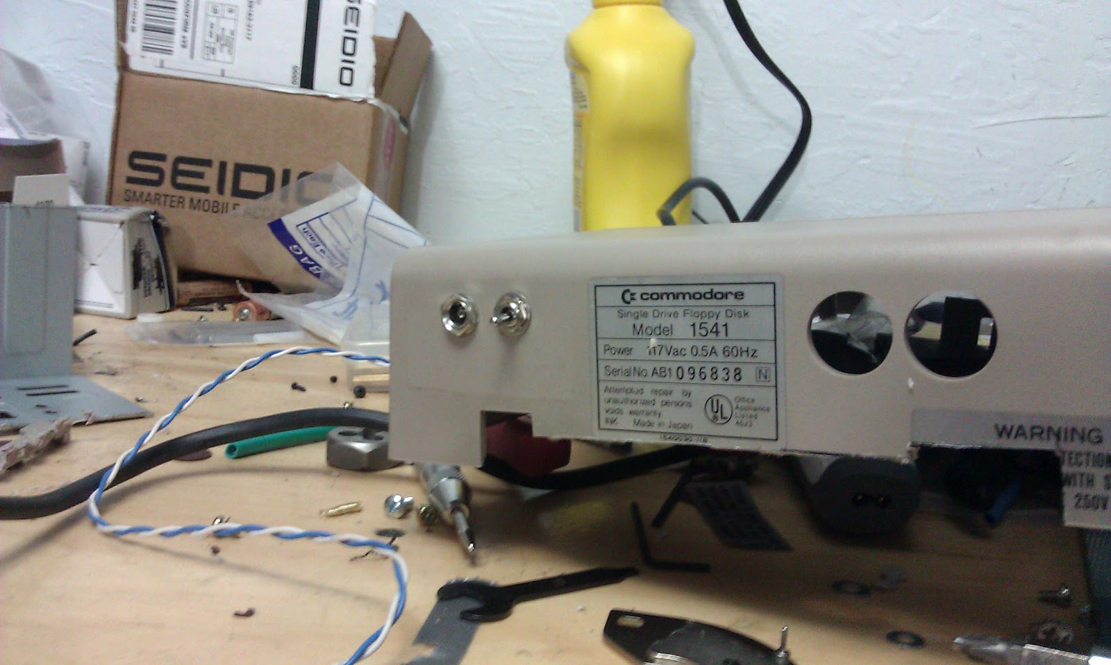
The power button can preform several operations. When the computer is sleeping it will wake it from sleep. When the computer is awake a quick tap will eject the CD/DVD/Blu-Ray from the drive. This is handy since there is no physical eject button I have access in the 1541. Holding it slightly longer will cause the computer to got to sleep. And if you hold it for a few seconds it will shut the computer down.
The board also displays several pieces of information. What Com port the board was detected on. What firmware version the board is reporting, link indicators that include sending and reviving data, as well as indicators for joystick activity.
The two joysticks are mapped to keyboard presses. They are configured to the default keyboard shortcut for the VICE keyboard joystick mapping. The keys can all be changed by clicking the remap joystick button.
I will be releasing all the source code and schematics for this board and application soon. I had packaged the boards firmware but am not releasing it as I added joystick support and that is not in the schematic. I do not believe I will be making any changes to the software on the board so as soon as I get the schematics done I will release the code. The windows application still needs a few tweaks before I release it but it is essentially done. I'm not much of a windows application developer so please don't laugh to much at my code. Once I mount the the 9 pin joystick connectors in the case I'll make a video of the final product.
This video shows an earlier version of the board (no joystick support) and an earlier version of the application.